
Camera Lens Testing — One Measurement, Every Optical Parameter
A camera lens that fails its specification tells you very little about why. An MTF curve that drops off-axis is a symptom shared by decentre, element tilt, air-gap error, field curvature and residual coma — and the curve itself does not distinguish between them. Production engineers get a pass/fail. The people who have to fix the process get a number they cannot act on.
Camera lens testing based on wavefront measurement inverts that. Instead of measuring one consequence of the pupil function, it measures the pupil function itself. From a single acquisition, modulation transfer function, point spread function, Strehl ratio, focal length, distortion, field aberrations and chromatism are all computed — and the Zernike decomposition names the aberration responsible.
Related Products
OEC VIS
R-FLEX

HASO 126 BROADBAND
What It Measures, and Where It Is Used
Two separate questions get conflated when instruments are compared: which quantities come out of the measurement, and at what point in a lens programme the measurement earns its place. They are listed separately below
Measured and derived parameters
- Wavefront error — on axis and across the field, zonal or modal
- Zernike and Legendre decomposition — astigmatism at 0° and 90°, coma at 0° and 90°, third-order spherical and higher orders, on circular or rectangular pupils
- Modulation transfer function — on and off axis, in 3D, at any azimuth and any defocus
- Point spread function and Strehl ratio — with spot geometry
- Focal length and back focal distance — from the curvature of the measured wavefront
- Distortion and field curvature — from field-sampled acquisitions
- Chromatism — longitudinal and lateral, measured at each wavelength of interest
- Intensity distribution across the pupil — vignetting and transmission non-uniformity, measured simultaneously with phase and independently of it
Use cases and applications across the lens lifecycle
- Prototype validation against design — compare measured Zernike coefficients directly with the ray-trace prediction, in the same vocabulary
- Assembly and alignment optimisation — live feedback while adjusting element spacing, tilt or centring
- Root-cause analysis on rejects — identify which aberration is driving a failure rather than confirming that one exists
- Incoming inspection — qualify supplied elements and subassemblies before they enter your build
- Shop-floor quality control — vibration-insensitive measurement outside a metrology lab
- Aperture and vignetting studies — track how performance changes with diaphragm setting
- Automated test station integration — measurement as a step in an existing handling and pass/fail sequence
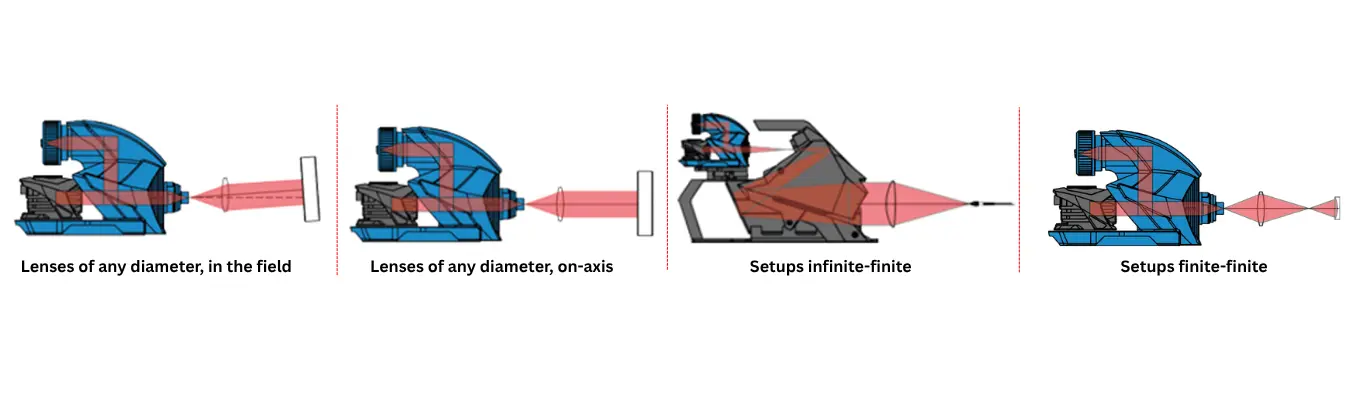
Optical setups for camera lens testing
Not sure which sensor and objective module your lens needs?
Send us the focal length, F-number, clear aperture and working wavelengths, and we will specify the configuration — including whether double pass is appropriate for your design.
Key advantages of Shack Hartmann measurement for lens testing
Shack-Hartmann wavefront sensing removes the reference arm entirely. A microlens array in front of a camera samples the local slope of the incoming wavefront at every subaperture; the wavefront is reconstructed from those slopes.
Three consequences matter for lens testing specifically.
- It measures phase and intensity simultaneously and independently.That patented capability is what makes derived parameters trustworthy — a wavefront reconstruction that is biased by intensity variation across the pupil would propagate that error into every computed quantity. It also means vignetting and transmission non-uniformity are characterised in the same acquisition, not inferred.
- It is insensitive to vibration and air turbulence.Each subaperture spot moves according to local slope, not according to optical path difference against a reference. A passing forklift shifts the whole measurement, not the fringe pattern. This is what lets the same instrument sit next to an assembly station.
- Measurement is absolute.HASO sensors carry embedded factory calibration and SpotTracker technology, which supplies absolute wavefront and tilt without a nulling procedure. There is no alignment ritual before a measurement is valid.
Why MTF Alone Does Not Tell You What Is Wrong With a Lens
MTF is the right criterion for image quality. The difficulty is where it sits: optical performance flows one way, from pupil function to PSF to MTF, and each transform discards information — phase when the PSF is squared, spatial structure when the contrast curve is extracted. Running that chain forward is deterministic; running it backward is not, which is why a low MTF reading identifies a reject but not a root cause. Measuring the wavefront recovers the pupil function directly, and everything downstream becomes a computation instead of a separate measurement.
That difference in entry point has consequences at the bench that rarely appear on a datasheet.
One housing, not a whole bench
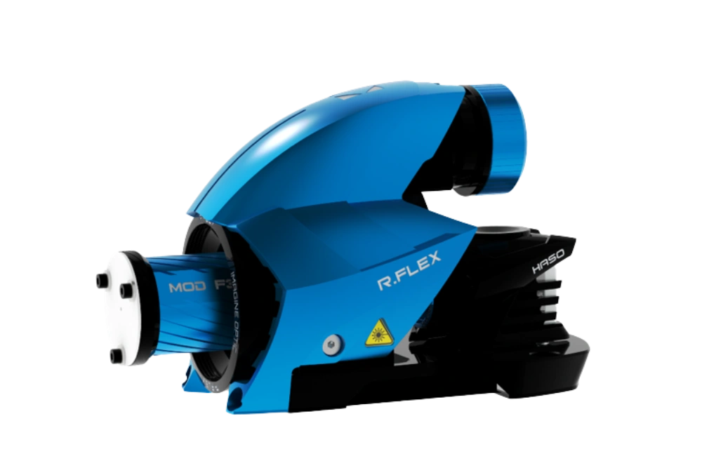
R-FLEX integrates source, collimator and sensor in a single body, replacing the goniometer arm, scanning stages and image-space optics a bench spreads along an optical table.
No nulling step
Embedded factory calibration and SpotTracker supply absolute wavefront and tilt, so there is no alignment procedure to repeat for every new part type.
Live, not sequential
Wavefront updates at video rate, so aberration changes on screen while a spacer or a tilt is adjusted — instead of waiting for a slit scan to rebuild each curve.
Works beside the assembly station
No reference arm, so vibration and air turbulence do not corrupt the reading. No optical table, no isolation, no dark room.
The whole focal region from one acquisition
The measured pupil function propagates to any defocus with nothing translated mechanically.
Any azimuth, plus full 3D MTF
Not only the tangential and sagittal orientations a slit or target defines.
Swap a fibre
The sensor is achromatic across its calibrated range, so there is no filter change and no recalibration between wavelengths.
Eight measurands, one acquisition
MTF, PSF, Strehl, focal length, back focal distance, distortion, field aberrations and chromatism — where a bench needs separate configurations for most of them.
Any optic that passes a beam
Collimators, beam expanders, windows, mirrors and laser sources — not only imaging lenses.
Nothing to calibrate out
The microlens array samples wavefront slope directly. No slit width, pixel MTF or readout noise sits between the lens and the number.
Names the aberration
A Zernike decomposition in the vocabulary the designer used to specify the part, instead of a contrast curve a reject shares with five possible causes.
Worked measurements
Rather than quote figures from one lens, which characterise that lens and not the method, we publish complete measurements with setup, raw data and analysis. The camera zoom lens study below documents the full procedure, including reference subtraction, off-axis field sampling and MTF derived from wavefront data across a range of diaphragm settings.
Lens system inspection with HASO R-FLEX — the worked camera lens measurement, with method and data.
Absolute measurement — why embedded factory calibration removes the nulling step.
How a Wavefront-Based Lens Test Works
Record the reference
With no lens in place, the beam is auto-collimated off a reference mirror and the wavefront recorded. This captures the intrinsic error of the metrology system itself — sensor, collimator and objective module — so it can be subtracted from every subsequent measurement. It is done once per configuration, not once per part.
Measure the lens
The lens under test is inserted and a flat mirror placed behind its focus. Light passes through the lens, reflects, and passes through a second time before reaching the sensor. The microlens array samples local wavefront slope at every subaperture, and the wavefront is reconstructed zonally or modally — in real time, without nulling and without an isolated table.
Derive every parameter
From that single pupil function, WaveView computes MTF, PSF, Strehl ratio, focal position and the full modal decomposition. Field points are added by translating the assembly; wavelengths by changing the fibre source. Nothing after step two requires touching the optical setup.
Software
WaveView — measurement, reconstruction and derived parameters
WaveView is supplied with every HASO sensor, R-FLEX and Optical Engineer Companion system. It provides zonal and modal wavefront reconstruction, real-time wavefront and intensity maps, modal coefficients on Zernike or Legendre polynomials, and full-pupil reconstruction even with random obstructions — useful for lenses with internal baffles, mechanical spiders or unusual aperture shapes.
The extensions that matter for lens testing are PSF (with Strehl ratio and spot geometry), MTF (including 3D MTF), Advanced Zernike for elliptical and annular pupils, and M² to ISO 11146 where a source rather than a lens is under test. Custom pupils can be defined with the pupil design tool, and sequential acquisition scripts let a field scan or a through-focus series run unattended.
WaveKit SDK — building it into a test station
Line-side testing rarely runs from an interactive GUI. WaveKit is a development kit in C/C++, Python and LabVIEW exposing the sensor and reconstruction primitives, so a wavefront measurement becomes a step in an automated test sequence with your own pass/fail logic, your own handler integration and your own data schema. This is the usual route for customers building the Companion into a production test bench.
Put a lens in front of one and see what it tells you
Send us the focal length, F-number, clear aperture and operating wavelengths of the lens you need to characterise. We will specify the sensor, objective module and platform, tell you what accuracy to expect, and be straight about whether wavefront metrology or a dedicated MTF bench is the better fit for your actual problem.
Frequently Asked Questions — Camera Lens Testing
How accurate is wavefront-based camera lens testing?
R-FLEX delivers λ/200 RMS measurement accuracy in double-pass configuration. The HASO sensors themselves carry absolute accuracy of λ/100 RMS with repeatability better than λ/200, achieved through embedded factory calibration rather than a user nulling procedure. Because the reference wavefront of the metrology system is recorded and subtracted, the figure quoted is the accuracy on the lens, not on the raw beam.
Is MTF measured or calculated?
Can this run on a production floor rather than in a metrology lab?
Yes, and that is a large part of why the technique exists. Shack-Hartmann sensing reconstructs the wavefront from local slopes rather than from optical path difference against a reference beam, which makes it insensitive to vibration and air turbulence. No optical table, no isolation, no dark room. The Optical Engineer Companion was built around this: no alignment, no optical table, no post-processing.
What wavelengths can we test at?
R-FLEX covers 400–1100 nm with a fibre-coupled source, and MS-LAMBDA offers five standard wavelengths with custom options on request. SWIR coverage is available through the Optical Engineer Companion SWIR and the HASO SWIR sensors. Since the wavelength is set by which fibre is connected, chromatism characterisation means running the same measurement three or four times, not buying three or four instruments.
Which lenses is this suitable for, and which are difficult?
Well suited: photographic and cine lenses, smartphone and module optics, machine vision lenses, automotive and ADAS optics, endoscope and medical optics, eyewear and smart glass. Harder cases are systems with very wide fields where point-by-point field sampling becomes slow, strongly vignetted designs, and geometries where a return mirror cannot be placed behind the focus. Send us the prescription and we will say plainly which category yours falls into.
Do we need a different system for each measurement?
No. The Optical Engineer Companion spans over 800 combinations from a common set of parts: any of seven HASO wavefront sensors, R-FLEX metrology systems, six R-FLEX LA collimating platforms for diameters from 30 to 200 mm, and a choice of metrology sources. Magnetic-isometric repositioning means switching between configurations is a snap-fit operation rather than a realignment.
Where a Dedicated MTF Bench Is Still the Right Tool
Wavefront metrology and direct MTF measurement are complementary, and a page that pretended otherwise would be wasting your time. Four cases genuinely favour a purpose-built MTF station such as those from Trioptics or Optikos.
Stray light and veiling glare do not appear in wavefront-derived MTF. This is the most important limitation and it is fundamental, not a specification gap. MTF computed from a pupil function describes what the designed optical path does. It does not capture light scattered from surface roughness, ghost reflections between elements, or glare from barrel interiors — all of which degrade real image contrast and all of which a slit-imaging measurement sees because it measures the actual image. For a lens where scatter is a suspected contributor, measure the image.
High-volume production gating. Dedicated benches are engineered around cycle time and traceability, with per-sample measurement in the low seconds and calibration traceable to international standards. If the requirement is to gate thousands of identical smartphone modules per shift against a contractual MTF number, that is what those instruments exist for.
Very wide fields and strong vignetting. Sampling a 120° field point by point through an auto-collimation setup becomes mechanically awkward. Multi-telescope architectures capture many field angles simultaneously by design.
Systems that cannot be measured in double pass. Strongly asymmetric designs, some catadioptric systems, and lenses where a suitable return mirror cannot be placed need a single-pass or image-space approach.
Blog Posts / Application Notes
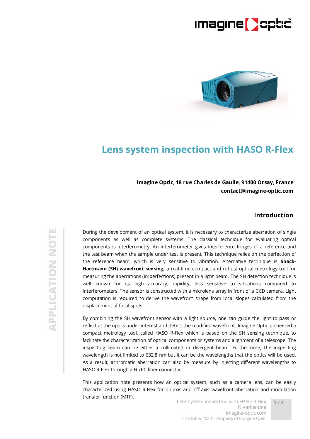
Lens system inspection with R-FLEX
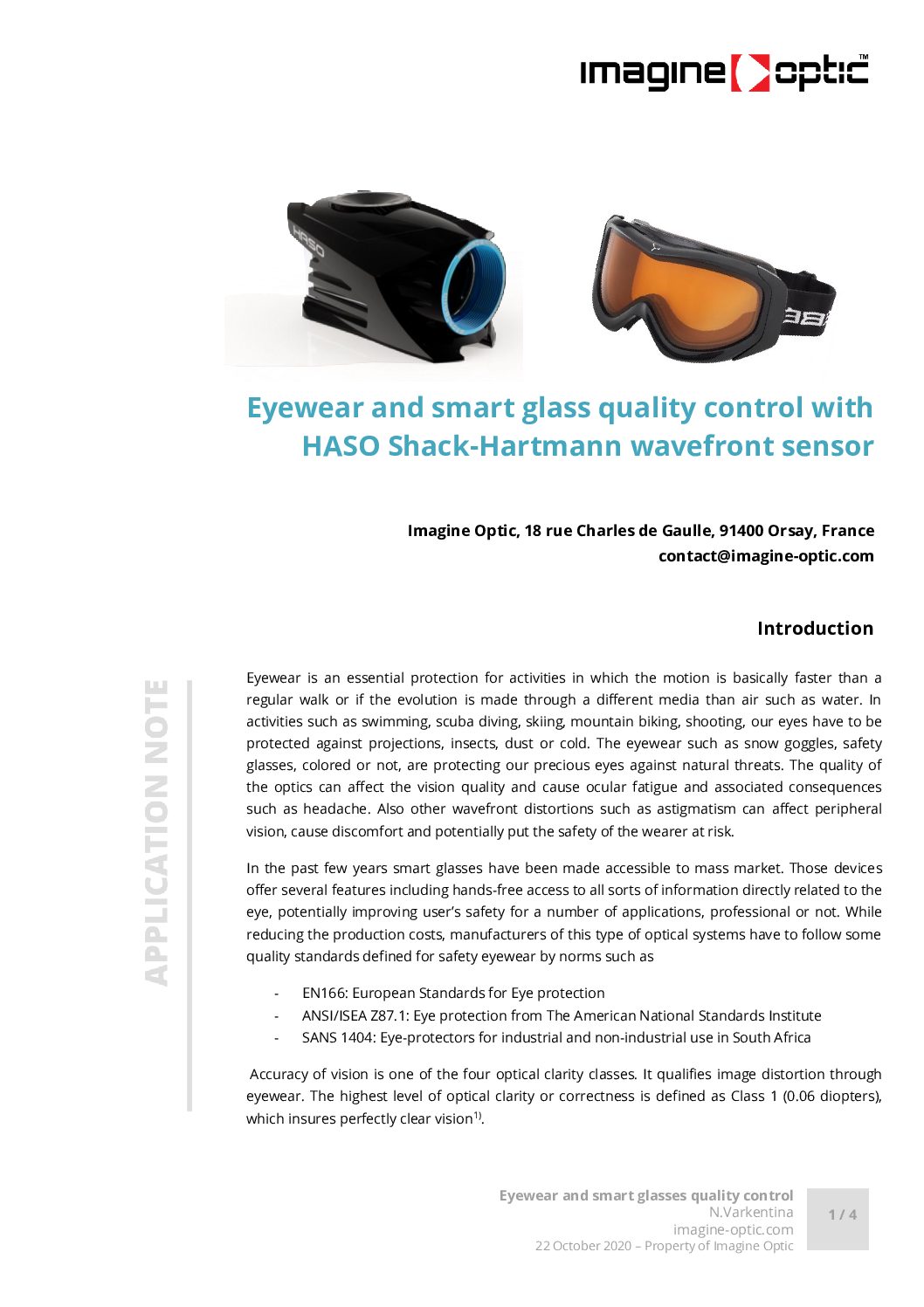
Eyewear and smart glass quality control
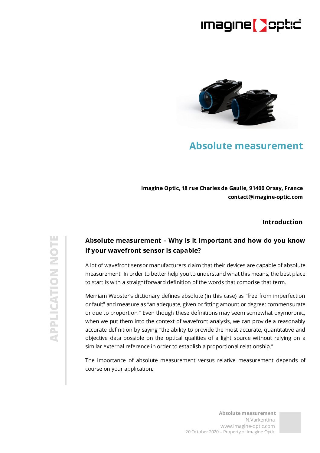
Absolute measurement
Related Applications
Screen Displays