Adaptive Optics for Space Situational Awareness (SSA) and Observation
Adaptive optics (AO) lets a ground-based telescope image satellites and space debris close to its diffraction limit, despite atmospheric turbulence. This page explains why space situational awareness (SSA) has become a priority, which objects AO can characterize in LEO, MEO and GEO, how bright those objects are, and how Imagine Optic’s CIAO VIS adaptive optics system brings this capability to telescopes up to 1 m in diameter.
Why monitor space from the ground?
Earth orbit has become a crowded place. According to ESA’s annual report, about 40,000 objects are currently tracked by surveillance networks, including about 11,000 active satellites. Yet the number of debris objects larger than 1 cm, which are large enough to cause catastrophic damage, is estimated at more than 1.2 million, of which only a little over 50,000 are larger than 10 cm. In 2025, more than 300 launches placed over 4,000 new payloads in orbit while the debris population keeps growing because fragmentation events create new debris faster than old debris naturally reenters the atmosphere. ESA also highlights a widening gap between the objects that are detected and those that can be identified, underscoring the need for better surveillance and space traffic management capabilities [1, 2].
Related Products

CIAO VIS
CIAO SWIR
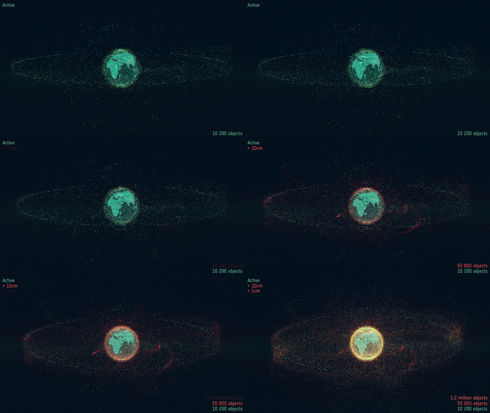
Distribution of space debris around Earth. Credit: ESA
Why is this a problem?
Orbital congestion has several direct consequences:
- The risk of collision is increasing: every tracked object could collide with an active satellite. Operators must therefore continuously analyze close approaches (“conjunctions”) and maneuver when necessary, knowing that every maneuver consumes fuel and shortens the satellite’s lifetime.
- Collisions create new debris: this phenomenon was described as early as 1978 by NASA scientist Donald Kessler: beyond a certain density of objects, each collision generates fragments that cause further collisions, in a self-sustaining chain reaction (the “Kessler syndrome”) [3]. According to ESA, this is now the greatest long-term threat: even with no new launches at all, the debris population would keep growing, and some orbital regions could become hazardous or even unusable. In its 2026 report, the agency revised upward its simulations of how the number of debris objects will evolve over the next 100 years compared with the previous year, and the runaway effect now appears much earlier [2].
- Everyday services are at risk: satellite navigation, telecommunications, weather forecasting, Earth observation: losing part of these orbits would have direct consequences on the ground. For the European Union, space surveillance is an essential security tool, in particular to protect its two flagship infrastructures: Galileo, the European satellite navigation system (Europe’s equivalent of GPS), and Copernicus, the Earth observation program dedicated to climate, the environment, and crisis management [4].


Galileo and Copernicus Sentinel-3. Credit: ESA
- Security and sovereignty are at stake: some satellites maneuver deliberately close to other satellites. Detecting and characterizing these approaches has become a strategic priority for many countries.
The purpose of SSA is therefore to know what is in orbit, where it is, and what it is doing: cataloging objects, predicting their trajectories, issuing collision warnings, detecting maneuvers, and characterizing objects (shape, attitude, condition). For characterization, high-resolution imaging is becoming essential.
Who does it?
On the public side, in Europe, the EU SST Partnership brings together 15 member states. France has chaired it since 2017 and, together with Spain, is responsible for collision risk assessment through the CAESAR service, operated by CNES’s orbit determination center in coordination with the French Space Command, whose GRAVES radar is a key asset [4]. In the United States, space surveillance is led by the military, which has long operated dedicated optical facilities. On the private side, the sector has grown considerably in recent years: in France alone, established players such as ArianeGroup and start-ups such as Aldoria, Look Up Space and Hemeria now provide commercial space surveillance data and services.
By what means?
Three main families of ground-based sensors complement one another: radars (suited to low Earth orbit, day and night), optical telescopes (essential for higher orbits, MEO and GEO), and laser ranging (highly precise distance measurement). But detecting and locating an object is no longer enough: we often need to know what it is. As ONERA points out, radar imaging alone is not sufficient for detailed characterization and identification of satellites, even in low Earth orbit, and optical imaging provides a powerful, complementary tool. This is where adaptive optics comes in [5].
Building or upgrading a space surveillance telescope?
Tell us your telescope diameter, f-number and target orbits. We will tell you what adaptive optics can resolve from your site.
A quick guide to orbits: LEO, MEO and GEO


| Acronym | Meaning | Typical altitude | Orbital period | Examples |
| LEO | Low Earth Orbit | ~200 to 2,000 km | ~90 min to 2 h | ISS, Starlink, Copernicus (Sentinel) |
| MEO | Medium Earth Orbit | ~2,000 to 35,786 km | a few hours to ~12 h | Galileo, GPS |
| GEO | Geostationary Earth Orbit | 35,786 km, above the equator | 24 h (synchronized with Earth’s rotation) | Telecommunications and weather satellites (Meteosat) |
Two other types of orbit worth knowing:
- SSO (Sun-Synchronous Orbit): a special case of LEO, near-polar, widely used for Earth observation (Sentinel, Pléiades).
- HEO (Highly Elliptical Orbit): a very elongated orbit, used for example to cover high latitudes.
For ground-based observation, each orbital regime has its own constraints. An object in LEO is close and therefore bright, but it crosses the sky in just a few minutes. An object in GEO appears motionless in the sky, but it is roughly 50 to 90 times farther away, and therefore much fainter.
Which satellites can your telescope image?
Send us your aperture and target list. We will match them against this magnitude table and the CIAO VIS limiting magnitude, and send back what is within reach.
State of the art of adaptive optics for space situational awareness (SSA)
The limiting factor: atmospheric turbulence
A ground-based telescope observes through the atmosphere, whose turbulence distorts the wavefront and limits the resolution to that of a telescope just a few centimeters across, regardless of its actual diameter. Adaptive optics (AO) measures these distortions in real time using a wavefront sensor and corrects them with a deformable mirror, bringing the instrument closer to its diffraction limit.
A technology born from space surveillance
AO is often associated with astronomy, but its history is closely tied to satellite observation. Much of its early development took place during the Cold War, in US military programs aimed at imaging and tracking satellites, notably at the Air Force’s Starfire Optical Range in New Mexico, a pioneering site for laser guide star AO. These techniques were later declassified and adopted by astronomers.
Current applications of adaptive optics for SSA
High-resolution imaging of satellites in low Earth orbit (LEO)
This is the flagship application. The Australian National University (ANU) developed the Adaptive Optics Imaging (AOI) system on a 1.8 m telescope at Mount Stromlo, which captures high-resolution images of objects in low Earth orbit to identify their features and estimate their size [6]. With AO, such a telescope can resolve objects around 40–50 cm in size at a range of 800 km [7]. In France, ONERA is working on LEO imaging, focusing on the challenge of fast-moving targets observed through the atmosphere and on post-processing of images whose PSF changes significantly during the observation [5]. This work has led to the PROVIDENCE project: a 2.5 m telescope optimized for Space Domain Awareness (SDA), to be installed at the Observatoire de Haute-Provence, with first light planned for late 2028 and a goal of decimeter-level resolution in LEO [8].
Laser ranging and debris tracking
Laser ranging measures the distance to an object in orbit with far greater precision than radar: a laser pulse is sent toward the debris and the round-trip time of the light is measured. The problem is that the return signal is extremely weak. For an object smaller than the beam, it falls off as A/r⁴ (where A is the object’s cross-section and r its distance), because the light spreads out on both the outbound and return paths. On top of this, turbulence broadens the uplink beam, spreading the energy even further around the target.

Here, AO is used to pre-correct the laser beam before it is launched, so that it arrives concentrated on the debris. Since a debris object is too faint to serve as a reference, turbulence is measured using a laser guide star: a second laser creates an artificial point of light in the upper atmosphere, in the direction in which the beam must be sent. The debris, illuminated by the Sun, is used only to correct the overall tilt of the wavefront (tip-tilt) [7].
Joint optical and processing design
Recent work by ONERA points out that AO correction is only partial and that deconvolution is often required, and proposes jointly optimizing the AO system and the image restoration algorithms [9].
Advantages and drawbacks of AO for SSA
| Advantages | Drawbacks / challenges |
| Near-diffraction-limited resolution: identification of shape, solar panels, and attitude | Very fast LEO targets: high angular velocity, rapidly changing turbulence along the line of sight, need for fast control loops |
| Direct complement to radar for characterization | Extended objects with variable brightness: wavefront sensing is more difficult than with a star |
| Improves the link budget for laser ranging (smaller telescopes, lower-power lasers) | Partial correction and variable PSF: post-processing (deconvolution) is almost always required |
| Mature technology, inherited from astronomy and defense | GEO: faint objects. ANU reports that GEO tracking could not be demonstrated on sky, as the satellites were too faint [6] |
| Also applicable to ground-to-space optical communications | Complexity, cost, high-speed tracking, and off-axis correction (the laser must be aimed ahead of the target) [7] |
How bright are satellites and space debris in orbit?
What determines a satellite’s apparent magnitude
A satellite does not emit light: it reflects sunlight. Its apparent magnitude therefore depends on three factors:
- its size (reflecting surface),
- its distance from the observer (the flux falls off as 1/R²),
- its reflectivity and the phase angle Sun–object–observer.
For an AO system that uses the object itself as its reference source, this magnitude directly determines feasibility. The wavefront sensor must receive enough photons in each loop cycle, and in LEO these cycles are very short.
Apparent magnitude by object size and orbit
|
Object size |
Example |
LEO 400 km (zenith) |
LEO 800 km (zenith) |
LEO, ~1,500 km range (low on the horizon) |
MEO (20,000 km) |
GEO (36,000 km) |
|
10 cm |
Debris, 1U CubeSat |
10 |
11.5 |
13 |
18.5 |
20 |
|
50 cm |
Small satellite, large debris |
6.5 |
8 |
9.5 |
15 |
16.5 |
|
1 m |
Microsatellite |
5 |
6.5 |
8 |
13.5 |
15 |
|
3 m |
Constellation satellite |
2.5 |
4 |
5.5 |
11 |
12.5 |
|
10 m |
Large satellite, rocket stage |
0 |
1.5 |
3 |
8.5 |
10 |
|
100 m |
ISS |
-5 |
– |
– |
– |
– |
Assumptions: the object is modeled as a diffusely reflecting (Lambertian) sphere whose cross-sectional area is d², where d is the size shown in the table, with an albedo of 0.2 and a phase angle of 45°. The apparent magnitude m is then given by the standard diffuse-sphere model [10]:
Where m is the apparent magnitude of the object in the V band, and:
- m⊙ = −26.74 is the Sun’s apparent magnitude
- ρ is the Bond albedo, the fraction of incident sunlight reflected by the surface
- d is the characteristic size of the object in metres, such that d² approximates its cross-sectional area
- R is the distance between the observer and the object, in metres
- φ is the phase angle in radians (the Sun–object–observer angle). At φ = 0 the object appears fully lit from the ground; at φ = π it is backlit.
The model correctly reproduces the order of magnitude of the ISS (about −5). It nevertheless represents a fairly favorable case. Real satellites are often 1 to 2 magnitudes fainter, due to lower albedo (dark coatings) and unfavorable phase angles. Conversely, they can briefly become much brighter during specular reflections off their solar panels (“glints”). This table should therefore be read with an uncertainty of about ±1.5 magnitudes.
CIAO VIS, the adaptive optics solution from Imagine Optic for satellite imaging
At Imagine Optic, we manufacture adaptive optics components such as deformable mirrors, wavefront sensors and loop control servers for closed-loop calculation.
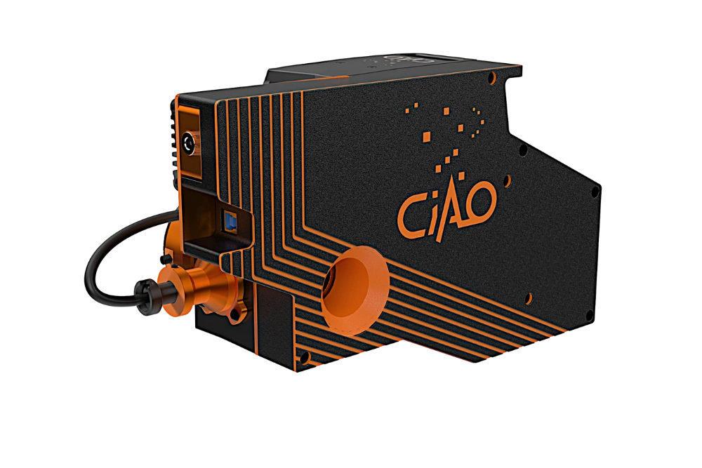
For this specific application, we developed and brought to market an all-in-one, plug-and-play adaptive optics unit that is easy to integrate at the interface of a telescope, the CIAO VIS system.
CIAO VIS Specifications |
|
|---|---|
| Spectral range | 400–1100 nm |
| Internal source | 520 nm |
| Deformable mirror | 40 piezo actuators |
| Max. closed-loop frequency | Up to 1 kHz |
| Average closed-loop delay | <1.7 ms |
| Rejection bandwidth cut-off | ≥45 Hz |
| Compatible telescope diameter | Up to 1 m |
| Input telescope f-number | Optimized for f/10 |
| Dimensions (L × W × H) | 372 × 232 × 152 mm³ |
| Weight | 4 kg |
It is a compact and lightweight system comprising a deformable mirror, a fast wavefront sensor and a server for loop calculations. It operates from 400 nm to 1.1 µm and is designed for up to 1 m class-telescope. With a loop running at up to 1 kHz, it corrects turbulence fluctuations up to 49 Hz (0 dB rejection bandwidth) and up to 40 modes.
It implements an internal source at 520 nm for internal checks and calibration.
However, with this unit, it is important to mention that it is specified for tracking objects with a limiting magnitude (faintest usable target) of 5 for a 500 mm class-telescope.
Adaptive optics systems for satellite imaging and optical links
CIAO VIS
Adaptive optics for satellite imaging
All-in-one, plug-and-play adaptive optics unit for telescopes up to 1 m, from 400 to 1100 nm. Deformable mirror, fast wavefront sensor and WaveSky loop server in a 4 kg unit, with tip-tilt offload to keep fast LEO targets centred on the imaging camera.
CIAO SWIR
Adaptive optics for optical links
The SWIR version of CIAO, from 1 to 1.7 µm, for ground-to-space optical communications and laser links, where the same turbulence that blurs satellite images reduces the power coupled into the receiver.
This simple formula gives, for any telescope size, the faintest target the wavefront sensor can use to close the loop:
With x the diameter of the telescope .
Worked example: the limiting magnitude is about 3.9 for a 300 mm telescope, 5.0 for 500 mm, 5.7 for 700 mm and 6.5 for 1 m. Read against the magnitude table above, a 500 mm telescope can lock on a 3 m constellation satellite in LEO between 400 and 800 km (magnitude 2.5 to 4), while a 1 m microsatellite at 800 km (magnitude 6.5) needs a 1 m telescope.
Combined with the apparent magnitude table, this tells you which targets your telescope can characterize and image at high resolution thanks to CIAO VIS. Our system is ideally suited to imaging LEO satellites larger than a few meters. Its offload feature drives a 5 Hz stepper-motor tip-tilt stage that keeps the target centered on the imaging camera during tracking.
The CIAO VIS is delivered with a computer with the WaveSky server installed on it, which is the server we developed for closed-loop calculations.
For more information about our product, see the CIAO VIS adaptive optics system page.
On-sky results with CIAO VIS – imaging the Tianhe space station
For any results with CIAO VIS, please check our dedicated gallery: CIAO Gallery. It includes an SSA result obtained with a 600 mm telescope: the target was the Tianhe Space Station at a minimum distance of 800 km in collaboration with ONERA and the OGS Feelings.

Image satellites from your own telescope
Send us your telescope diameter and f-number and our team will check which LEO targets CIAO VIS can lock on, using the magnitude table above. Request a CIAO VIS demo or quote.
Image satellites from your own telescope
Send us your telescope diameter and f-number. Our team will check which LEO targets CIAO VIS can lock on, using the magnitude table above.
Request a CIAO VIS demo or quoteSee the CIAO galleryFrequently Asked Questions — Adaptive Optics For SSA
What does adaptive optics do for space situational awareness?
It corrects the atmospheric turbulence that limits a ground-based telescope to the resolution of an instrument a few centimeters across. A wavefront sensor measures the distortion and a deformable mirror cancels it in real time, so the telescope works close to its diffraction limit and can resolve a satellite’s shape, solar panels and attitude.
Can adaptive optics image satellites in low Earth orbit?
Yes. LEO imaging is the main SSA application of adaptive optics. With AO, a 1.8 m telescope can resolve objects around 40–50 cm in size at a range of 800 km [7]. The difficulty is speed: LEO objects cross the sky in a few minutes, so the correction loop must be fast.
Why are GEO satellites harder to characterize than LEO satellites?
GEO objects are roughly 50 to 90 times farther away than LEO objects, so they are much fainter. A 3 m satellite is around magnitude 12.5 in GEO, too faint for most AO systems that use the target itself as the wavefront reference.
What is the faintest target CIAO VIS can use?
The limiting magnitude is 5 on a 500 mm telescope and increases with aperture, to about 6.5 on a 1 m telescope. CIAO VIS is therefore ideally suited to imaging LEO satellites larger than a few meters.
Can CIAO VIS be installed on an existing telescope?
Yes. CIAO VIS is an all-in-one, plug-and-play unit of 4 kg that integrates at the telescope interface. It is optimized for f/10, compatible with telescopes up to 1 m in diameter, and delivered with a computer running the WaveSky control server.
References
[1] ESA Space Debris Office, “ESA Space Environment Report 2025,” European Space Agency, April 1, 2025. https://www.esa.int/Space_Safety/Space_Debris/ESA_Space_Environment_Report_2025
[2] ESA Space Debris Office, ESA’s Annual Space Environment Report, Issue 10, Rev. 0, May 1, 2026. Summary: “ESA Space Environment Report 2026,” September 14, 2026. https://www.esa.int/Space_Safety/Space_Debris/ESA_Space_Environment_Report_2026
[3] D. J. Kessler and B. G. Cour-Palais, “Collision frequency of artificial satellites: The creation of a debris belt,” Journal of Geophysical Research, vol. 83, no. A6, pp. 2637–2646, 1978. doi:10.1029/JA083iA06p02637
[4] CNES, “Space Surveillance and Tracking,” updated January 17, 2025. https://cnes.fr/en/projects/sst
[5] C. Petit, L. Mugnier, et al., “LEO satellite imaging with adaptive optics,” ONERA, HAL open archive, hal-03206079. https://hal.science/hal-03206079
[6] M. Copeland, Satellite and Debris Characterisation with Adaptive Optics Imaging, PhD thesis, Australian National University, 2020. https://openresearch-repository.anu.edu.au/items/e41713ca-a9a0-426d-93ac-81dd90a4ba5b
[7] F. Bennet, C. d’Orgeville, I. Price, F. Rigaut, I. Ritchie, and C. Smith, “Adaptive optics for satellite imaging and space debris ranging,” in Proc. Advanced Maui Optical and Space Surveillance Technologies Conference (AMOS), 2015. https://amostech.com/TechnicalPapers/2015/Adaptive_Optics_Imaging/Bennet.pdf
[8] C. Petit et al., “PROVIDENCE: toward a 2.5m adaptive telescope for optical space domain awareness (but not only…),” Proc. SPIE 13097, Adaptive Optics Systems IX, 130970N, 2024. doi:10.1117/12.3019661
[9] F. Cheyssial, L. Mugnier, and C. Petit, “Joint optical-digital design strategy for adaptive optics systems: application to wavelength selection for satellite imaging,” Optics Express, vol. 34, no. 3, p. 4895, 2026. arXiv:2602.06537
[10] J. Šilha, P. Jevčák, M. Zigo, T. Hrobár, and A. Szilágyi-Sándor, “Photometric phase functions of resident space objects and space debris extracted from brightness measurements,” in Proc. Advanced Maui Optical and Space Surveillance Technologies Conference (AMOS), 2023. https://amostech.com/TechnicalPapers/2023/Poster/Silha.pdf
Blog Posts / Application Notes

Optimizing the coupling efficiency into a single-mode-fiber

Adaptive optics for Free Space Optics… and for fun!
Related Applications
Free Space Optics & SATCOM
