Adaptive Optics for Free-Space Optical Communication (FSO)
Free space optical communication (FSO)
Free-space optical communication (FSO) enables the transmission of high-frequency light signals over long distances, such as between two optical ground stations (OGSs) or between a satellite and an OGS. To collect the light, we use a telescope, and at the output of it, we couple the light into a single-mode fiber (SMF) for its compatibility with current SMF-based optical communication technology. In addition, their narrow core allows only one guided mode, eliminating modal dispersion and leading to high bandwidth capability (they offer transmission capacities that are wider by a factor of at least 100 compared to multimode fibers) and low attenuation. Coupling the beam into a SMF at the receiver also allows for the full use of erbium-doped fiber amplifiers (EDFA) and coherent mixers, which are key components in high-performance FSO systems.

Space to ground communication
Related Products

CIAO SWIR

HASO SWIR FAST

NASA’s Low-Cost Optical Terminal, Photo: NASA
The data collection is feasible during both nighttime and daytime.
However, unlike the radio frequency (RF) commonly used for telecommunications, FSO is restricted by the weather, like the presence of fog for instance. In contrast with RF communication, FSO operates in a license-free spectrum, immune to microwave/RF interference and other FSO links due to the narrow beam divergence and transmits high data rates up to 100 Gbps.
In FSO, high frequency wavelength is privileged because of the resistance of the signal propagation to fog (reduced scattering in light fog). In addition, 1.55 µm wavelength are usually used for safety reasons, as our cornea acts as an optical band-pass filter passing wavelengths ranging from 0.4 to 1.4 µm, longer wavelengths with high power do not impact the retina.
Atmospheric turbulence, a major obstacle for FSO
In the atmosphere, the photons may encounter diverse obstacles such as absorption by molecular constituents as water vapor, fog etc., or scattering, background noises, and the effect of turbulence. Within the troposphere, the concentration of particles is higher near the Earth surface and it decreases with increasing altitude up through to the ionosphere.
When the Sun heats the ground, the air immediately above it warms up and begins to rise. This warm air, buoyed by Archimedes ‘principle, then collides with and mixes with the cooler surrounding atmosphere, giving rise to the phenomenon we call “atmospheric turbulence”. This manifests as a variation of index of refraction due to temperature inhomogeneity, atmospheric pressure and wind velocities. The optical signals temporal intensity is thus fluctuating a lot, referred as scintillation or fading. A classic illustration of this phenomenon is the ‘twinkling’ of stars, where atmospheric turbulence distorts the incoming starlight.
The sensitivity of the receiver telescope is defined as the minimum amount of optical power needed to achieve a specified level performance, and is quantified by the bit error rate (BER). However, atmospheric turbulence can significantly degrade the BER by inducing wavefront aberrations and pointing errors. For context, while an ideal target BER is on the order of 10⁻⁹, severe turbulence can degrade this performance to as high as 10⁻³
During daytime operations, optical downlinks experience stronger background solar radiation and elevated ground-level turbulence. Consequently, spectral filtering via an ultra-narrowband optical transmission filter, combined with adaptive optics correction, is required to minimize the focal spot size of the downlink beam.
How adaptive optics can be the solution?
The effect of the atmospheric turbulence is non negligible, especially if one has to couple into a SMF at the output of a telescope, with a tiny core of about 10 µm. Coupling a distorted wavefront into a SMF leads to a significant reduction in coupling efficiency, resulting in substantial signal attenuation.
To correct the disturbed incoming light, we rely on adaptive optics (AO) principle. For an object from space, the wavefront is disturbed and not planar (flat). To retrieve a diffraction limit like image, we first analyze the incoming wavefront with a wavefront sensor and with a controller, apply the inverse shape of the wavefront to compensate the deformation with a deformable mirror. Correction is efficient if the loop runs as fast as the speed of the turbulence. The AO principle is illustrated in the figure below, using the image of Neptune from ESO as a reference.

Adaptive optics principle
The solution we offer at Imagine Optic: CIAO SWIR
At Imagine Optic, we offer an AO solution adapted for FSO application which is the CIAO SWIR device, a compact AO system that can be plugged at the output of the telescope and runs up at 3.5 kHz. It operates in the 1.0 to 1.7 µm, adapted for up to 1 meter class telescope with an input f# of f/9 to f/12. At the output of it, you can directly inject into a SMF and optimize the coupling efficiency by having control over the Non-Common Path Aberrations accessible via the WaveSky software, delivered with the device.
The output port of CIAO can be reconfigured to be adapted to your own coupler, collimated or converging beams are possible.
Several filter holders in the optical path are accessible by the user to add extra wavelength filtering in the case CIAO is used as a pre-compensator for the uplink
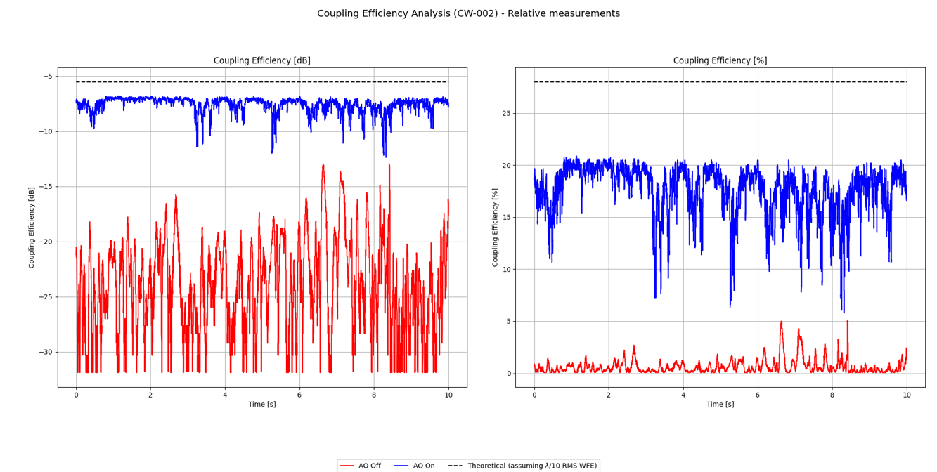
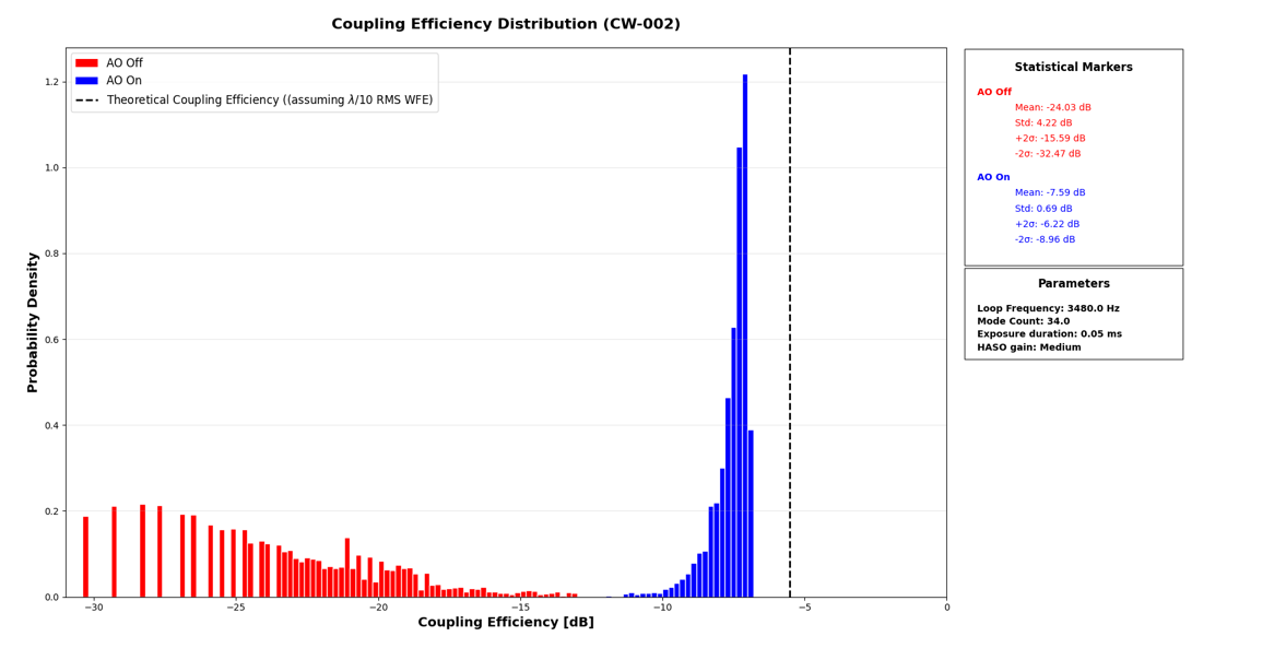
Results we achieved with CIAO SWIR:
Without AO, the turbulence causes strong losses in the coupling efficiency (up to -15 dB in the best cases, which do no occur often, as shown by the height of the right-most red bar).
With AO turned on, the average coupling efficiency is much better (-7.6 dB without -24 dB without AO), and the “spread” in coupling efficiency (how wide the distribution is) is much smaller. Meaning we are able to reach good coupling efficiency reliably.
CIAO SWIR in the lab - The setup
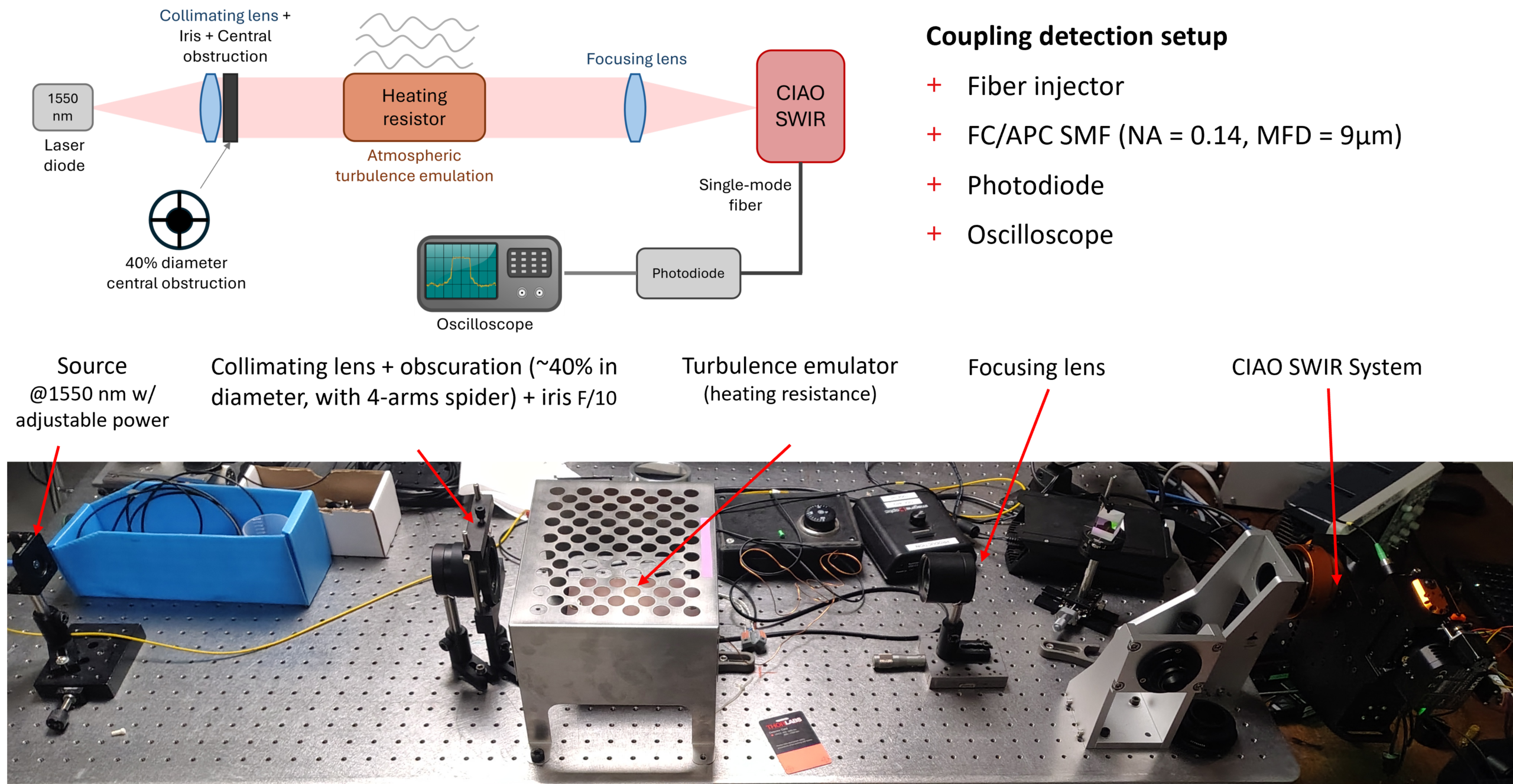
 (1)")
Coupling efficiency with and without Adaptive Optics
Coupling efficiency displayed as a histogram
PSF without AO (left) compared to PSF with AO (right)
Frequently Asked Questions — Adaptive Optics for FSO
Is it possible to change the dichroic beamsplitter?
Yes, if the substrate has 1’ diameter and 5mm thick.
What fiber connector is used (e.g., FC/APC, SC/APC)?
FC-APC is used
Is it possible to have something else at the CIAO output (other than fiber output)? For example, if we want to perform other processing before injection into the fiber?
It can be part of a customisation agreement. As an additional information, the injection lens has an aperture of f/3.6, also customizable.
What is the typical coupling efficiency at 1550 nm after AO correction?
The best we measured is about -3dB (CIAO internal loss not included). This really depends on the atmospheric turbulence and especially how fast they are. For horizontal link FSO, the wind speed is critical. CIAO rejection bandwidth cut-off at 0dB is 115Hz. On a 200mm diameter telescope, we can expect no gain from CIAO for wind speed above 23m/s as the turbulence is fully uncoherent.
In general, the telescope tracks a satellite using a camera. How good/accurate does this coarse alignment/tracking need to be for the OA to work? 1 arcsec? 10 arcsec?
The dynamic range of the deformable mirror in tilt is ~+/- 5 µm PTV (Peak-to-Valley) when used across its full diameter (which is the case with an f/9.2 telescope). This corresponds to +/- 2 arcsec on a 500mm telescope. If the mount is less precise, one can also use the ‘Fine Tracking’/’Offload’ mode (tip/tilt mirrors). Our CIAO SWIR’s datasheet mentions a tracking precision of +/- 1 arcmin, which is the ‘hard’ limit even with tracking via the tip/tilt motors.
Can the CIAO output port accepts external laser injection for the transmit path?
No, CIAO is basically an Rx terminal. It has not been designed to be used as a Tx terminal.
Does the CIAO system include a Fast-Steering Mirror (FSM)? We need control over the FSM to enable our point-ahead for Tx laser comm, is that possible with yout current software or will that be added cost to modify your software control?
CIAO does not include an FSM, the deformable mirror is used to remove the tilts created by turbulence.
We can inject the Tx signal in CIAO to use the same DM as a turbulence pre-compensator for the Tx signal. To manage the PAA (Point-Ahead Angle), an additional tip-tilt mirror must be added only on the Tx optical path. All this can be done but a large modification of the existing fiber holder must be designed, manufactured and tested.
Such a modification will probably and very roughly double the price of CIAO SWIR and will need from your side some work in terms of specifications.
Blog Posts / Application Notes

Optimizing the coupling efficiency into a single-mode-fiber

Adaptive optics for Free Space Optics… and for fun!
Related Market

Observation & Space situational awareness
References
[1] Czerwinski, A. (2025). Atmospheric modeling of free-space optical transmission: satellite downlinks and horizontal channels. Optical and Quantum Electronics, 57(10), 577.https://doi.org/10.1007/s11082-025-08505-5
[2] Ghassemlooy, Z., & Popoola, W. O. (2010). Terrestrial free-space optical communications. Mobile and Wireless Communications Network layer and circuit level design, 17, 355-391.
[3] Wei Liu, Wenxiao Shi, Jingtai Cao, Yaowen Lv, Kainan Yao, Shuai Wang, Jihong Wang, Xuefen Chi (2014) . Bit error rate analysis with real-time pointing errors correction in free space optical communication systems, Optik, Volume 125, Issue 1, 324-328, ISSN 0030-4026. https://doi.org/10.1016/j.ijleo.2013.06.043.
[4] Gladysz, Szymon & Zepp, Andreas & Bellossi, Raphael & Segel, Max & McDonald, Douglas & Stein, Karin. (2022). Adaptive optics for daytime deep-space optical communications. 3. 10.1117/12.2633036.